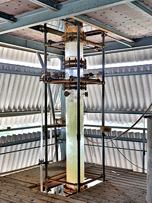
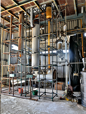
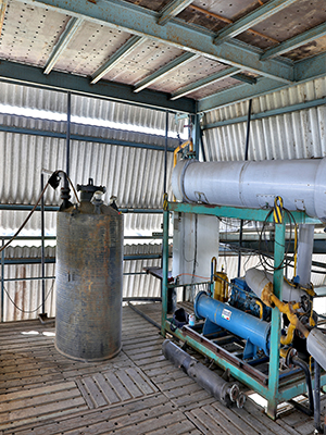
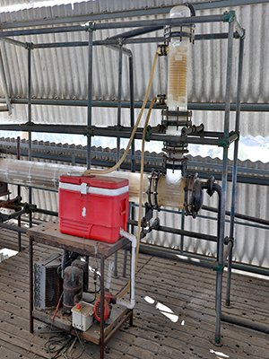
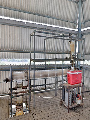
Anhydrous HCL Gas Generation Plant
Gas Absorption Anhydrous HCL Gas Generation Plant
Anhydrous HCL Gas Generation Plant
(CaCl2 Process) (Zero Discharge-NIL Effluents)
(Process option-1)
The plant has been designed as a continuous process to produce dry HCL gas by the process of distillation of 30% hydrochloric acid solution along with a co-current stream of Calcium chloride solution.
30% hydrochloric acid solution is fed to the azeotropic distillation column (C-1).The feed is pre-heated by steam in the heat exchanger (E-1).Simultaneously a co-current feed of concentrated calcium chloride is also fed to the distillation column.
The calcium chloride breaks the azeotrope formed between HCL and water and as a result almost all the HCL available in the solution is released as gas.
The shell and tube type of heat exchangers (E-1 and E-4) are designed as a thermosiphon reboilers where the heat energy for the distillation process and the evaporation process is supplied by steam.
The vapour from the reboiler strips the available gas from the feed acid solution in the column. The top product HCL gas is dried in the Drying Unit using a suitable dehydrating agent. The moisture content in the product HCL gas is expected to be less than 0.001%.
The bottom product from the column (C-1) is dilute calcium chloride solution with some HCL content. The dilute CaCl2 solution is concentrated in the evaporator (E-4) and the re concentrated CaCl2 solutionis recycled to the distillation column by pump (P-2).
The vapour from the evaporation process consists of water and expected to contain less than 1% HCL. The water vapour is condensed in the heat exchanger (E-5) prior to discharge. Thesystem selected is very stable. Once all the operating conditions are stabilized and maintained; rate of generation of HCL gas depends only upon rate of hydrochloric acid (30%) feed.
The system turn-down ratio is high.
All the wetted parts of the system are fabricated from corrosion resistant materials (Glass and PTFE)
Consumption figures (per kg of Product HCL Gas)
- Inputs – 30% w/w Hydrochloric acid :3.42 kg.
- Utilities – Steam: 6.0 kg CW/Chw.
- Output – Effluent: Water containing 1%: 2.41 kg.
- Floor Space Area – 3 M X 2 m Overall height being 11.5 meters.
- Salient features:
- No Effluent.
- Zero Discharge.
- Lowest operating cost.
Dry HCL Gas Generation Plant (Distillation Of 30% HCL Process)
(Process option-2)
The plant has been designed to produce dry HCL gas by the process of distillation of 30% hydrochloric acid solution.
The plant has been designed to operate as a continuous process.
The feed 30% hydrochloric acid solution is pre heated by the outgoing hot bottom product in the heat exchanger (E-3) and fed to the azeotropic distillation column by the pump. The feed rate is controlled.
The shell and tube type of heat exchanger (E-1) is designed as a thermosiphon reboiler where the heat energy is supplied by steam.
The vapour from the reboiler strips the available gas from the feed acid solution in the column.
The bottom product from the plant is constant boiling 20% acid solution which is cooled in (E-3) by the cold 30% acid feed solution prior to discharge.
The top product HCL gas is dried in the Drying Unit using a suitable dehydrating agent. The moisture content in the product HCL as is expected to be less than 0.001%.
The system selected is very stable.
Once all the operating conditions are stabilized and maintained; rate of generation of HCL gas depends only upon rate of hydrochloric acid (30%) feed.The system turn-down ratio is high. All the wetted parts of the system are fabricated from corrosion resistant materials (Glass and PTFE).
Consumption Figures(per kg of Product HCL gas)
- Inputs – 30% w/w Hydrochloric acid: 8.0 kg.
- Utilities – Steam 2.0 kg CW/ChW.
- Output – Effluent20% w/w HCL:7.0 kg.
- Floor Space Area – 2m X 1m Overall height 10.5 m.
- Salient features:
- Low capital cost.
- Simple Process.
- Compact Design.
- No H2SO4required as feed material.
- Pure 20% HCL as bottom product.
- Low operating cost.
Dry HCL Gas Generation Plant (H2SO4)
(Process-3)
The plant is designed to produce dry HCL gas (moisture content<0.001%) by the process of dehydration of 30% hydrochloric acid solution with concentrated sulphuric acid.
The plant is designed to operate as a continuous process.
Controlled quantity of concentrated sulphuric acid is fed from top to the packed column. A co-current feed of 30% hydrochloric acid solution is also fed to the column.
HCL gas is generated when the two liquid acid feeds come in contact. The top portion of the packed column acts as a dehydration zone for the product HCL gas.
Suitable column internals like liquid re-distributors as well as mist eliminator sections have been provided in the design.
Heat Exchanger (E-1) has been designed as gas cooler operating on cooling water/chilled water.
The bottom product from the plant is spent sulphuric acid approx. 70% acid solution. (with 1-1.5% HCL content) which is cooled in heat exchanger (E-2) prior to discharge.
The system selected is very stable. Once all the operating conditions are stabilized and maintained; rate of generation of HCL gas depends only upon rate of hydrochloric acid (30%) feed.
The system turn-down ratio is high.
All the wetted parts of the system are fabricated from corrosion resistant materials ( Glass and PTFE).
- Inputs – 30% w/w Hydrochloric acid : 3.5 kg.
98% w/w Sulphuric acid : 5.7 kg. - Utilities – Steam : Nil CW/ChW.
- Output – Effluent : 70% w/w spent sulphuric acid ( containing approx..1-1.5% HCL) : 8.2 kg.
- Floor Space Area – 1.5 m X 1 m Overall height 7.5 m.
- Salient features:
- Low capital cost.
- Simple process.
- Dry gas available without drying unit.
- Very compact Design.
- Large quantity of sulphuric acid required to be handled.
- Effluent with HCL impurity.
- Load on effluent treatment plant.
- Higher operating cost.
